Here is a concise cheat sheet summarizing the processor acceleration concepts, with key diagrams from the documents included.
🚀 Processor Acceleration Cheat Sheet: From MAC to GPU
1. The Instruction Pipeline
The foundation for high performance is the instruction pipeline. It breaks instruction processing into stages (e.g., Fetch, Decode, Execute, Write). This allows the processor to work on multiple instructions at different stages simultaneously, increasing throughput.
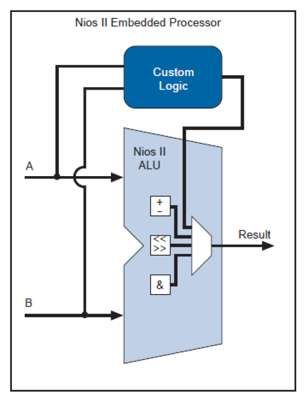
2. Custom Instructions (CI)
A Custom Instruction accelerates a specific, frequently-used software function by implementing it directly in hardware.
-
It connects directly to the processor’s main ALU.
-
It receives inputs from registers and writes the result back in a single clock cycle.
-
Example: Converting an RGB pixel to grayscale, which involves multiple shifts, multiplications, and additions, can be reduced to one custom hardware instruction.
3. Multiply-Accumulate (MAC) Unit
This is a dedicated hardware unit for the operation, which is the “bedrock” of Digital Signal Processing (DSP) and AI (Neural Networks).
-
Superscalar (e.g., ARM Cortex-A53): The MAC unit is its own pipeline, separate from the main integer ALU. This allows the processor to execute a MAC instruction and an integer instruction at the same time.
-
VLIW (Very Long Instruction Word): Found in DSPs. The compiler creates a single, very long instruction that explicitly tells multiple units (e.g., two MACs, two load units) what to do in parallel in the same cycle.
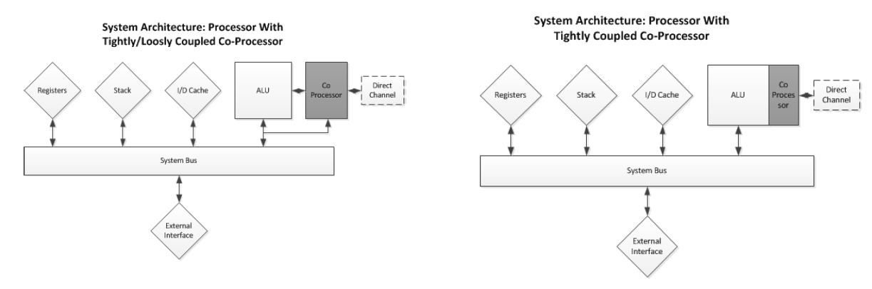
4. Co-Processors
A co-processor is a separate processing unit that has its own instruction set and instruction decoder1111. It assists the main CPU by handling specific, complex tasks.
- Integration Types:
- Tightly-Coupled: The co-processor is integrated directly into the host CPU’s instruction pipeline2. The host processor “knows” the co-processor’s instructions3.
- Loosely-Coupled: The co-processor sits outside the main pipeline, often on the system bus4. It can be memory-mapped, where the CPU writes data to shared memory, triggers the co-processor, and then fetches the result from memory when it’s ready.
- Classic “Loose” Execution Flow:
- The main CPU fetches an instruction and its decode stage signals “unidentified instruction”.
- The CPU asks all attached co-processors if one of them can handle this instruction.
- If no co-processor claims it, the CPU throws an “unrecognized op-code” exception.
- If a co-processor claims it, the instruction is passed to that co-processor for execution.
- The main CPU may stall if it finds another co-processor instruction while the co-processor is still busy.
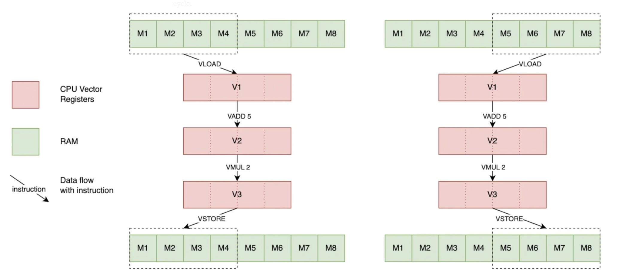
4. Single Instruction, Multiple Data (SIMD)
Details on SIMD (vector) processing, using ARM NEON as an example:
- Integration: SIMD units are typically tightly-coupled co-processors. In an ARM Cortex-A53, the Neon (SIMD) unit is its own dedicated pipeline, parallel to the main integer and MAC pipelines.
- Registers and Lanes:
- The interface between the CPU and the SIMD unit is a bank of large registers (e.g., 64-bit or 128-bit).
- These registers are treated as a vector containing multiple independent lanes of a smaller data type.
- For example, one 128-bit register can be treated as
uint16x8_t(eight 16-bit integers) oruint8x16_t(sixteen 8-bit integers). - A SIMD instruction operates on all lanes simultaneously, with no data crossing between lanes.
- Programming with Intrinsics:
- SIMD operations are accessed in C/C++ using intrinsics like
uint16x4_t. - An intrinsic is a function that looks like a C function call but maps directly to a single assembly instruction.
- Example: The intrinsic
vaddl_s8(a, b)wraps theSADD(Saturating Add) instruction.
- SIMD operations are accessed in C/C++ using intrinsics like
- Overflow and Saturation:
- SIMD operations can cause overflows or underflows, but they do not set overflow flags like a traditional ALU.
- Wrapping (Default): The value wraps around (e.g., an 8-bit
255 + 1becomes0. - Saturation (Specific Instructions): The value is “clamped” to the maximum or minimum value for its data type (e.g., an 8-bit
250 + 10becomes255). A flag is set in a status register (not the main ALU flags) when saturation occurs.
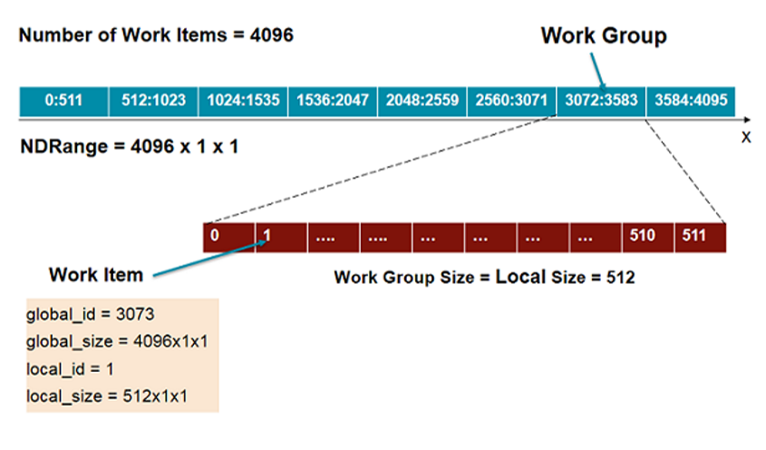
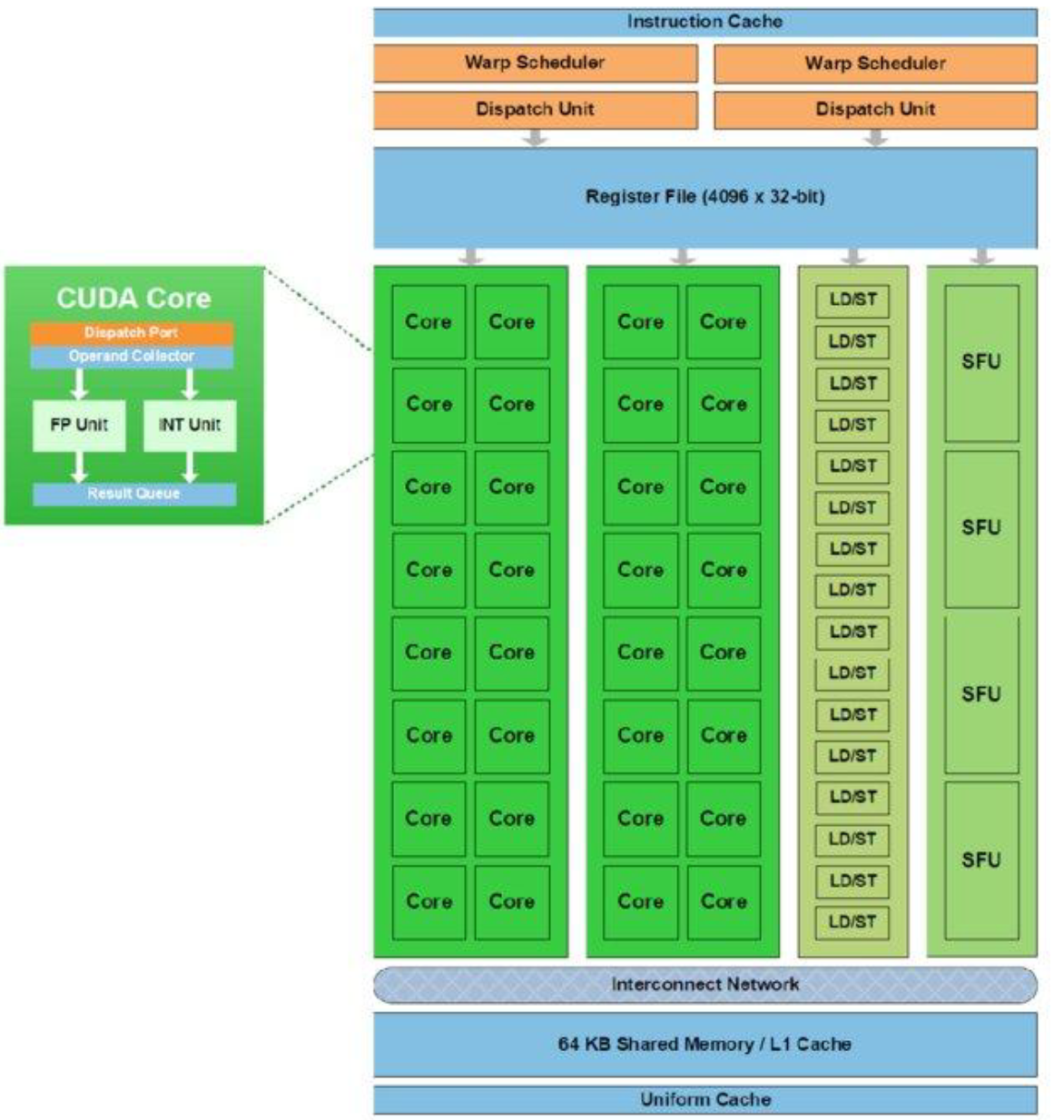
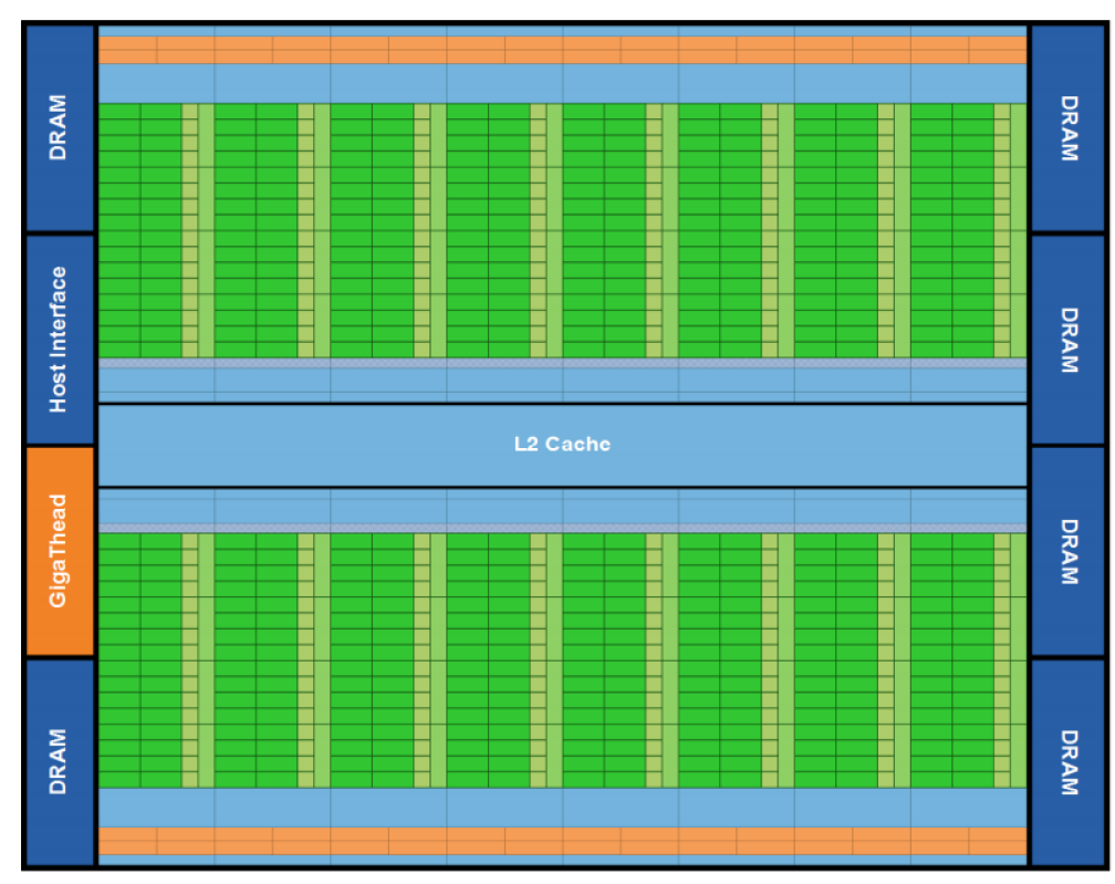
6. Graphics Processing Units (GPU)
A GPU is a massively parallel “many-core” device. It uses a Single Program, Multiple Threads (SPMT) model.
- Host (CPU): Sends data and a special function, called a Kernel, to the Device (GPU).
- Kernel: A C-like function that is executed by thousands of threads in parallel.
- Work Item: A single thread executing the kernel.
- Work Group: A collection of threads.
- NDRange: The total number of threads launched.
Multicolumn
Blank
Blank
Blank
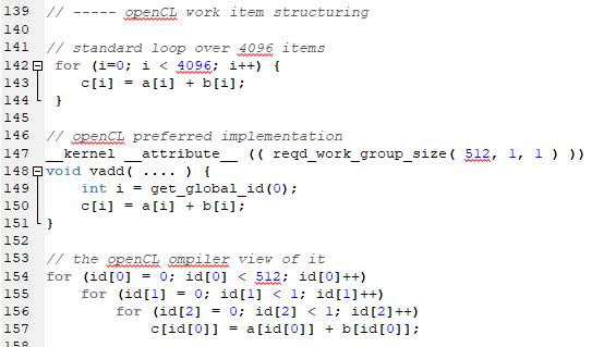
Loop to Kernel Conversion:
A standard for loop on the CPU is converted into a kernel. Each thread finds its own ID to determine which loop iteration it is responsible for.
-
Standard C Loop:
for (int i = 0; i < N; i++) { C[i] = A[i] + B[i]; } -
OpenCL Kernel (GPU Code):
size_t globalSize = N;     // total threads
size_t localSize = 64;     // threads per work group (optional, usually a multiple of 32 or 64)
clEnqueueNDRangeKernel(queue, kernel, 1, NULL, &globalSize, &localSize, 0, NULL, NULL);

__kernel void vector_add(__global const float* A,
                         __global const float* B,
                         __global float* C,
                         const int N) {
    int i = get_global_id(0); // unique thread ID
    if (i < N) {
        C[i] = A[i] + B[i];
    }
}