Structural analysis
Meshing
Only use necessary mesh sizing, it will converge on the same value with finer mesh.
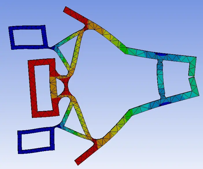
90 inner angles will create singularities and equivalent stress will rise with smaller mesh size. (Force act on no surface)
Bias for mesh sizing, merge mesh hard or soft
Span angle center : for radius, create finer mesh
<1M nodes = petit modèle
Mesh defeaturing : useful when 90 angle can be vereinfacht, avoid singularities..
in general, we need local mesh settings to have sufficient results
Method
Change meshing method : Mesh > method
Patch conforming: all edges (Kanten) in cad will create nodes frontiers in mesh (for tetraedrons)
Hex Dominant mesh : only use for parts with big volumes (not Blech for example)
Sweep : for prismatic bodies (same surface on top and bottom)
Multizone : autodetect were to sweep the model
Cartesian : do a cartesian Netz and quetch on the body (not really useful, maybe for 3d printed pieces, multiple layers)
Metrics display :
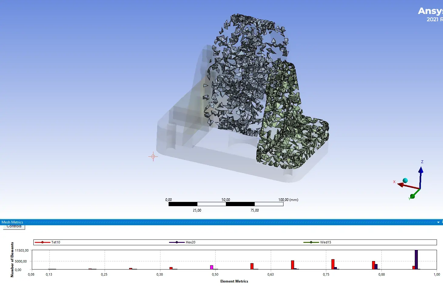
Press on the graph bar, to show some that are less good (first half of graph)
Inflation : when two pieces are pressed together, near holes for example
Face meshing : for faces with 4 edges
In general: try to reach a mesh that “looks” good, have finer mesh where data will be read.
Loads
A force is distributed on all the surface nodes selected, and will always point in the same directoin
A pressure, is always perpendicular to the surface, even if the deformation is big
Remote force → connect all nodes to a remote force (crée des moments)
Contacts
If 2 bodies are not bonded, the problem becomes not linear
Tips
Never do screw dimensioning in FEM, just read the forces on the beam and do the Nachweis by yourself
Modal analysis
About Eigenfrequenz analysis
Contacts are made of springs, which should be removed (Contact region > Formulations): select MPC for multi body connected in modal analysis
Grosse influence à cause des prétentions (en provenance d’un modèle structurel) et des appuis
Grosse Verformung
Die Reaktionkräfte verhandern sich mit grossen Verformungen !
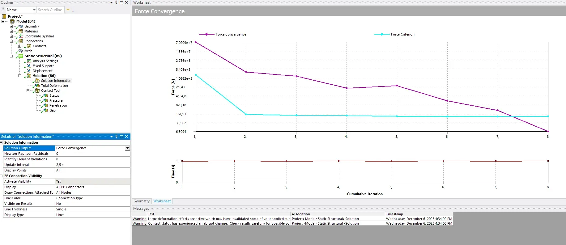
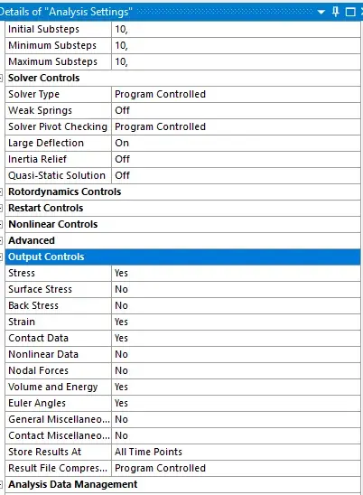
Analysis settings → activate large deflection
Iterative solutions necessary → take longer
Solution Information > solution Output > Force convergence
Contacts between components often lead to non linear systems
Non-linear materials (plastic Bereich) : super-elastic materials
We need to work with the iterative diagram in system analysis to see at which step the model converged to a solution. For exemple, a 10 mm displacement will be divided into a lot of smaller displacement steps to solve.
Tips
Contacts
The problems becomes non-linear !!
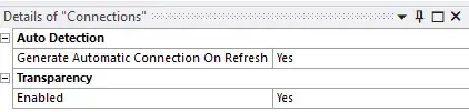
Often deactivate the auto detection of contacts
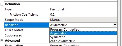
use bonded and frictionless or frictional
Select large deflection !
the mathematical model can be interpreted with some springs
can lead to oscillation in the simulation (the more rigid, the more problematic)
we need hard spring when we want to know the precise force on the contact
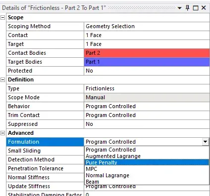
we can change normal stiffness (of the springs)
more stiff → harder to solve
Drag and drop
Drag the connection to the results to see the force reaction
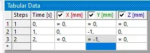
Force at different timestamps
analysis settings > two steps
right click on data and deactivate at timestamp 2
Analysis output
select all to yes
Material properties
Change material property to non linear (stress curve is bilinear) → let us see the plastic deformation of a piece