The Avalon interconnect fabric is an open standard that defines multiple interface modes for connecting soft IP components in a System-on-a-Programmable-Chip (SoPC), ensuring IP interoperability.
Multicolumn
Blank
Avalon Interface Overview
Concept Explainer: The Avalon interconnect fabric is a method for connecting soft IP components and is an open standard defining multiple interface modes to handle all interactions of IPs within a SoPC.
Interaction Modes Used in SoPCs:
Clock Interface: Methods to clock synchronous elements (e.g., Avalon Clock Interface).
Conduit Interface: For asynchronous communication and sharing connections (e.g., Avalon Conduit Interface).
Streaming (ST): For transferring data as fast as possible (e.g., Avalon-ST).
Tri-State Connection (TC): Method to share a connection between multiple external elements to reduce I/Os (e.g., Avalon-TC).
Memory-Mapped (MM): To realize host/agent (master/slave) interactions for memory access and control register communication (e.g., Avalon-MM).
The Purpose of an Avalon Conduit Interface
Concept Explainer: Avalon Conduit interfaces group an arbitrary collection of signals for asynchronous communication. They are typically used to drive off-chip device signals (e.g., SDRAM control signals).
Critical Highlight: When connecting conduits, roles and widths must match, and directions must be opposite.
Signal Role
Width
Direction
Description
any
arbitrary
in, out, bidirectional
A conduit consists of one or more input, output, or bidirectional signals of arbitrary width and any user-specified role.
Attach Custom IP to Avalon-MM
Concept Explainer: Avalon-MM provides a method to transfer data from software (host/master) to a custom IP (agent/slave) over the Avalon fabric.
Transfer Types:
A transfer is a read or a write operation.
The interface is synchronous.
Communication Model (Polling):
Also known as software-driven I/O.
Used for interacting with slow external elements.
Simple, uses few signals, but results in CPU busy-wait.
Avalon-MM Transfer Modes: Fixed-cycle delay, dynamic-delay, and burst-transfer modes.
Agents can stall the transfer:
Using the waitrequest signal (dynamic delay). If used for one, must be used for both read/write.
Using fixed wait-states (readWaitTime/writeWaitTime), making waitrequest unnecessary.
Blank
AVALON-MM ELEMENTS
Supported elements include: Microprocessors, Memories, UARTs, DMAs, Timers, and Custom IPs.
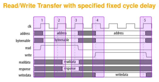
FIXED-CYCLE DELAY: Read Transfer ( readWaitTime = 1)
Cycle 1 Start: Host asserts address and read.
Cycle 2 Start: Marks the end of the wait-state cycle.
Cycle 3 Start: Agent asserts readdata and response. Read transfer ends.
FIXED-CYCLE DELAY: Write Transfer ( writeWaitTime = 2)
Cycle 4 Start:writedata, address, byteenable, and write are asserted.
Cycle 7 Start: The write transfer ends after 2 wait state cycles.
Cycle 7 Start: Agent captures writedata, ending the transfer.
Avalon-MM Agent Signal Roles
Concept Explainer: An Avalon-MM agent interface uses signals corresponding to unique signal roles.
Critical Highlight: Active low signals end with _n (e.g., reset_n).
Signal Role
Width
Direction
Description
clk
1
Input
Clock signal.
reset, reset_n
1
Input
Resets internal logic.
address
1-32
Host → Agent
Byte address (Host), converted to word address (Agent).
read, read_n
1
Host → Agent
Asserted for a read transfer.
readdata
8, 16, 32, …
Agent → Host
Read data from agent.
write, write_n
1
Host → Agent
Asserted for a write transfer.
writedata
8, 16, 32, …
Host → Agent
Data for write transfer.
waitrequest, waitrequest_n
1
Agent → Host
Asserted by agent to halt transfer until ready.
2: The PIO-IP as example of an Avalon-MM Agent
BIG PICTURE
The PIO (Parallel Input Output) IP serves as an example to demonstrate the design and integration of a custom, configurable IP block into an SoPC using the Avalon-MM interface and VHDL.
Multicolumn
Blank
PIO Design Specifications (Specs)
Concept Explainer: The PIO-IP is a configurable 8-bit parallel port for external elements (LEDs, buttons). It supports bidirectional communication with per-bit software-programmable direction.
Key Features:
Bidirectional: Fixed size of one byte (8 pins).
Programmable Direction: Set per pin via software (SW).
IRQ Generator: Core is extendable with an IRQ generator.
Register Model Registers:
RegDir (Control): Sets direction (0: input ∣ 1: output). Read/write access. Default is input.
RegPort (Data): Stores the output value. Read/write access.
RegPin: Reads the current state of the external port pins. Read-only.
RegSet: Write sets specified bits of RegPort to ‘1’ (OR operation).
RegClr: Write sets specified bits of RegPort to ‘0’ (AND NOT operation).
Programmable Interface Design Method
Concept Explainer: The design follows a structured flow from hardware signal identification (VHDL entity) to a software-accessible register model and final VHDL architecture development.
Design Steps:
Identify I/Os: Define the VHDL entity signals.
Define Register Model: The HW/SW interface (Control, Status, Data registers). Avoid unnecessary hardware complexity.
Create Architecture: Implement control logic and data paths (e.g., derive outputs from registers, write registers from inputs).
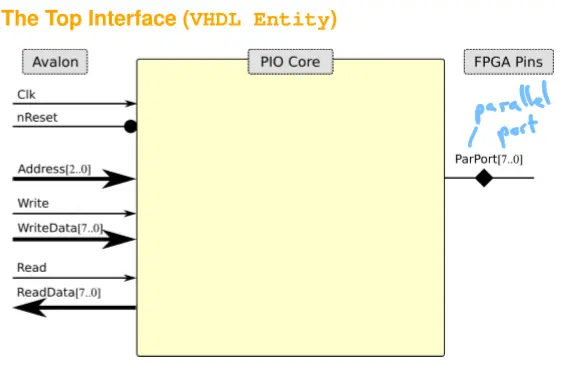
PIO VHDL Entity (Interface)
Concept Explainer: The VHDL entity defines all external connections. The signals are derived from the IP block diagram.
Signal Declarations: Use only std_logic and std_logic_vector. VHDL Entity Code:
library ieee;use ieee.std_logic_1164.all;entity SimplePIO isport ( -- Avalon interfaces signals Clk_CI : in std_logic; Reset_RLI : in std_logic; Address_DI : in std_logic_vector (2 DOWNTO 0); Read_SI : in std_logic; ReadData_DO : out std_logic_vector (7 DOWNTO 0); Write_SI : in std_logic; WriteData_DI : in std_logic_vector (7 DOWNTO 0); -- Parallel Port external interface ParPort_DIO : INOUT std_logic_vector (7 DOWNTO 0));end entity SimplePIO;
PIO Register Address Map
Concept Explainer: The PIO requires 3 address bits for 0×0 to 0×7 addressing. NIOS II uses 4-byte word alignment.
Addr
Write Name
Write Reg [7..0]
Read Name
Read Reg [7..0]
0×0
RegDir
→RegDir
RegDir
→RegDir
0×1
-
Don’t care
RegPin
→ParPort
0×2
RegPort
→RegPort
RegPort
→RegPort
0×3
RegSet
→RegPort
-
0×00
0×4
RegClr
→RegPort
-
0×00
0×5
-
Don’t care
-
0×00
0×6
-
Don’t care
-
0×00
0×7
-
Don’t care
-
0×00
Blank
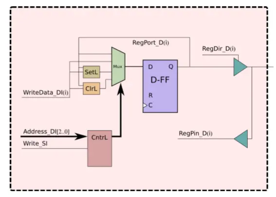
VHDL Architecture (noWait)
Concept Explainer: The architecture binds the entity signals to internal components (RegDir_D, RegPort_D, RegPin_D) using internal signals.
Register Write Logic (pRegWr)
Detailed Explanation: This synchronous process handles reset and register writes on the rising clock edge when Write_SI is active. It implements the address decoder based on the register map.
pRegWr: process(Clk_CI, Reset_RLI)beginif (Reset_RLI = '0') then -- Default: Input by default RegDir_D <= (others => '0'); RegPort_D <= (others => '0');elsif rising_edge(Clk_CI) then if Write_SI = '1' then case Address_DI(2 downto 0) is when "000" => RegDir_D <= WriteData_DI; when "010" => RegPort_D <= WriteData_DI; when "011" => RegPort_D <= RegPort_D OR WriteData_DI; when "100" => RegPort_D <= RegPort_D AND NOT WriteData_DI; when others => null; -- Handles invalid address patterns end case; end if;end if;end process pRegWr;
Read Data Logic (Fixed Zero Cycle Delay)
Detailed Explanation: This approach yields a purely combinatorial output with a fixed zero-cycle delay. The interconnect layer will handle synchronization.
-- Read from registers with wait 0ReadData_DO <= RegDir_D when Address_DI = "000" else RegPin_D when Address_DI = "001" else RegPort_D when Address_DI = "010" else (others => '0');
Read Data Logic (Fixed One Cycle Delay)
Detailed Explanation: This synchronous process implements a fixed one-cycle delay by registering the output value, storing it before it travels to the host.
pRegRd: process(Clk_CI)beginif rising_edge (Clk_CI) then ReadData_DO <= (others => '0'); if Read_SI = '1' then case Address_DI (2 downto 0) is when "000" => ReadData_DO <= RegDir_D; when "001" => ReadData_DO <= RegPin_D; when "010" => ReadData_DO <= RegPort_D; when others => null; end case; end if;end if;end process pRegRd;
Parallel Port I/O Logic (pPort)
Detailed Explanation: Implements the software-controlled tri-state logic for each pin using a tri-state output buffer and input buffer. Output mode is set by RegDir_D(i) = '1'; input mode (set by ‘0’) results in high impedance (‘Z’).
pPort: process (RegDir_D, RegPort_D)beginfor idx in 0 to 7 loop if RegDir_D(idx) = '1' then -- Output mode (1) ParPort_DIO (idx) <= RegPort_D(idx); else -- Input mode (0) ParPort_DIO (idx) <= 'Z'; -- High-impedance output end if;end loop;end process pPort;-- Parallel Port Input value captureRegPin_D <= ParPort_DIO;