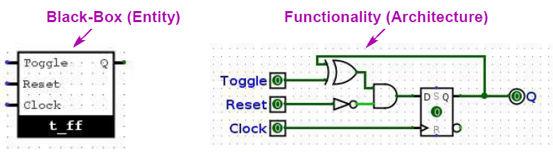
The black-box of the digital circuit is the ENTITY, the functionality inside the black-box is defined in the ARCHITECTURE.
ENTITY and ARCHITECTURE have the same ports, it defines their relationship. Entity and architecture can be in the same file or separate.
LIBRARY ieee;USE ieee.std_logic_1164.all;USE ieee.numeric_std.all;-- Entity declarationENTITY entity_name IS PORT ( port_name_1 : in port_type_1; port_name_2 : out port_type_2; B_DO : out signed(25 DOWNTO 0)); port_name_n : inout port_type_n );END entity_name;-- Architecture declarationARCHITECTURE architecture_name OF entity_name IS -- Declare components here -- Declare signals and constants hereBEGIN -- Instantiate components with portmap here -- Describe behavior of entity using processes, -- functions, and assignmentsEND architecture_name;
Def
VHDL is case insensitive
Only letters, numbers and underscore for variables
outputs can’t be read !
Assign same signal twice create a shortcut
Operators & Types
Multicolumn
Blank
Operators
Operator
Description
Example
=,/=,<,<=,>,>=
relational
s_data = 0;
and,or,xor
Logical
a <= b and c;
nand,nor,xnor
Logical
a <= nand c;
not
Logical inverse
a <= not c;
<=
Signal assignment
a <= b;
=>
assign 0
a <= (others => ‘0’)
:=
Variable assignment
a := b;
+,-,*,/
Math, never use /
a <= b + c;
mod
Modulo
a <= b mod c;
rem
Remainder
a <= b rem c;
**
Exponentiation
a <= b ** c;
&
Concatenation
a <= b & c;
sll,srl
Shift logical
a <= b sll c;
sla,sra
Shift arithmetic
a <= b sla c;
rol,ror
Rotate
a <= b rol c;
Blank
Predefined data types
Data Type
Range/Characteristics
bit
'0', '1'
bit_vector
(bit, bit, ..., bit)
boolean
true or false
character
'A'-'Z', 'a'-'z', '0'-'9'
integer
−231 to 231−1
natural
0 to 232−1
positive
1 to 232−1
real
±1×10−38 to ±3.4×1038
signed
−2n−1 to 2n−1−1 signed(<nr_of_bits-1> DOWNTO 0)
unsigned
0 to 2n−1 unsigned(<nr_of_bits-1> DOWNTO 0)
string
Array of characters
time
Format: hr:min:sec:ms:us:ns:ps:fs
numeric_std
Defined in
Used for numerical computations and variables within a process.
Assigned using := operator.
Update immediately within the process.
Not sensitive to changes in inputs.
Used for sequential computations within a process.
Signals & Constants
Multicolumn
Blank
Signal types
Signal Type
Possible Values
Bit
std_logic
n-Bit Bus
std_logic_vector( (n-1) DOWNTO 0 )
Values
’0’=0, ‘1’=1, ‘U’=Undefined, ‘X’=Unknown, ’-‘=Don’t care, ‘Z’=High Z
Used for data flow and inter-process communication.
Assigned using <= operator.
Represent concurrent processes.
Have inherent timing characteristics and update values after a delta delay.
Sensitivity to changes in inputs.
SIGNAL <s_name> :<signal_type>;SIGNAL <si_name>, <s_name>,... :<signal_type>;
Good practice to use s_mySignal. Signal have types std_logic or std_vector.
Blank
Constants
Good practice to start each constant name with the prefix c_.
-- Signal definitionSIGNAL s_myBus : std_logic_vector(23 DOWNTO 0);-- Assign constant value using binary notations_myBus <= "100000000000000000000000";-- Assign constant value using hexadecimal notations_myBus <= X"800000";-- Assign constant using mix of binary and hexs_myBus <= X"80" & "0000" & X"000";-- Assign constant value using the macro OTHERSs_myBus <= (23 => '1', OTHERS => '0');-- Assign part of the vectors_myBus(1 DOWNTO 0) <= "10";-- Assign bit 1s_myBus(0) = '1';
Multiplexer
Multicolumn
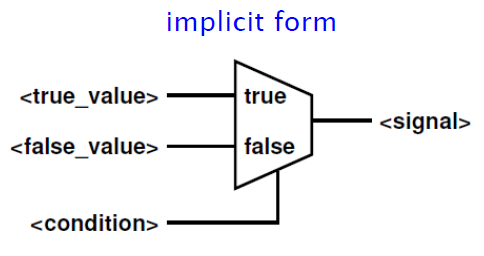
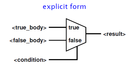
Implicit / Explicit
-- Implicit MUX<mySignal> <= <true_value> WHEN <condition> ELSE <false_value>;-- Explicit MUXIF <condition> THEN <true_body>ELSE <false_body>END IF;
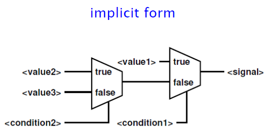
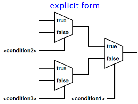
Nested
-- Implicit nested MUX<mySignal> <= <value1> WHEN <condition1> ELSE <value2> WHEN <condition2> ELSE <value3>;-- Explicit nested MUXIF <condition1> THEN IF <condition2> THEN... ELSE... END IF;ELSIF <condition3> THEN...ELSE...END IF;
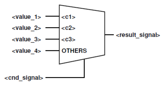
Unconditional
-- Implicit unconditional MUXWITH <cnd_signal> SELECT <result_signal> <= <value_1> WHEN <c1>, <value_2> WHEN <c2>, <value_3> WHEN <c3>, <value_4> WHEN OTHERS;-- Explicit unconditional MUXCASE <cnd_signal> IS WHEN <c1> => result_signal <= value_1; WHEN <c2> => <body_c2>; WHEN <c3>|<c4> => <body_c3>; WHEN OTHERS => <body_default>;END CASE;
Memory
Multicolumn
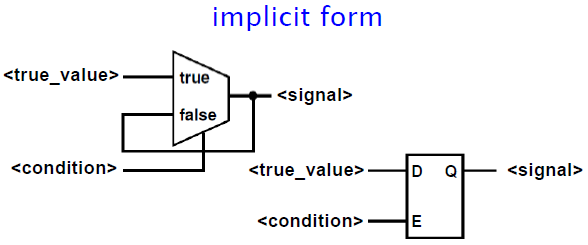
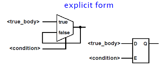
D-Latch
-- Implicit<mySignal> <= <true_value> WHEN <condition>;-- Explicit IF <condition> THEN <true_body>END IF;
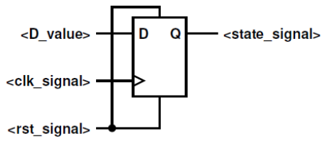
D-FlipFlop Async Reset
-- Implicit UNUSUAL but possible<state_signal> <= <rst_value> WHEN <rst_signal> ='1' ELSE <d_value> WHEN rising_edge(<clk_signal>);-- Explicit BETTER !dff: PROCESS(<rst_signal>,<clk_signal>) IS BEGIN IF(<rst_signal> ='1') THEN <state_signal> <= <rst_value>; ELSIF (rising_edge(<clk_signal>)) THEN <state_signal> <= <d_value>; END IF;END PROCESS dff;-- Only use rising_edge with clock signals
Blank
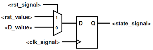
D-FlipFlop Sync Reset
-- Implicit UNUSUAL but possible<state_signal> <= <rst_value> WHEN (rising_edge(<clk_signal>) AND <rst_signal> ='1') ELSE <d_value> WHEN rising_edge(<clk_signal>);-- Explicit BETTER !dff:PROCESS(<clk_signal>) IS BEGIN IF (rising_edge(<clk_signal>)) THEN IF (<rst_signal> = '1') THEN <state_signal> <= <rst_value>; ELSE <state_signal><= <D_value>; END IF; END IF;END PROCESS dff;-- Only use rising_edge with clock signals
Process & Loops
Multicolumn
Blank
Loops and special statements
Be careful, loops are executed in parallel, not like software !!!
-----For loop-----------for i in (MAX-1) downto 0 loop y(i) <= a(i) xor b(i)end loop;-----While loop---------while error_flag /= '1' and done /='1' loop Clock <= not Clock; wait for CLK_PERIOD/2;end loop;-----Infinite loop------loop -- if someting then use exit; keywordend loop;----Other statements----wait on signals;wait until Boolean_expr;wait for time_expr;exit; -- exit loop
Components
Components are used to instantiate entities inside a top level entity.
ARCHITECTURE id_name OF TOP_entity_name IS --component declaration COMPONENT <entity_name>IS PORT(<port_1>; ... <port_n>); END COMPONENT;BEGIN --component instantiation <instance_name> : <entity_name> PORT MAP (<port_1> => <TopLevelSignal_1>, ... <port_n> => <TopLevelSignal_n>);END id_name;
Blank
Process Logic
Processes allow to define execution order of sequential statements, in order to simulate the behaviour on a processor. The sigma iterator enables simulating parallel systems on sequential machines using δ-representatives. The δ iterator in VHDL processes represents time steps during simulation.
It starts at zero and increments by one for each iteration. The inputs from sensitivity list are replaced by the fixed δ−event value as soon as an event is fired.
The outputs are replaced by a δ-representatives (<signal_name>δ) at each iteration.
Statements in a process are evaluated sequentially based on δ-representative values.
Iteration continues until a stable state is reached with no new events.
Final signal values are assigned to actual signals at the end of the process.
SR-Latch Example
ENTITY sr_latch IS PORT(s, r : IN std_logic; q, q_bar : OUT std_logic);END ENTITY sr_latch;ARCHITECTURE behavioral OF sr_latch IS SIGNAL q_int, q_bar_int : std_logic;BEGIN q <= q_int; q_bar <= q_bar_int; sr_latch_process : PROCESS(s, r) IS BEGIN IF r = '1' THEN q_int <= '0'; q_bar_int <= '1'; ELSIF s = '1' THEN q_int <= '1'; q_bar_int <= '0'; END IF; END PROCESS sr_latch_process;END behavioral;
Design & FSM
Multicolumn
Blank
Generic design
We can implement a generic bloc to describe a paremeterized circuit. Many synthesis tools only supports INTEGER.
ENTITY name IS GENERIC (<GenericName> :<dataType>; <GenericName> :<dataType> := <defaultValue>; ...); PORT (<portName> :<portType> <signalType>; ...);END name;-- ImplementationARCHITECTURE multiCount OF example IS COMPONENT GenericCounter IS GENERIC (MaxState : INTEGER; NrOfBits : INTEGER; ResetState : INTEGER; OutState : INTEGER); PORT (clock,R,E : IN std_logic; X : OUT std_logic); END COMPONENT;-- Other declarations and statements BEGIN counter1: GenericCounter GENERIC MAP (MaxState => 432, NrOfBits => 9, ResetState => 356, OutState => 10) -- no ; here PORT MAP (-- Port connections for couter1); counter2: GenericCounter GENERIC MAP (....) PORT MAP (-- Port connections for couter2); -- Other architecture codeEND multiCount;
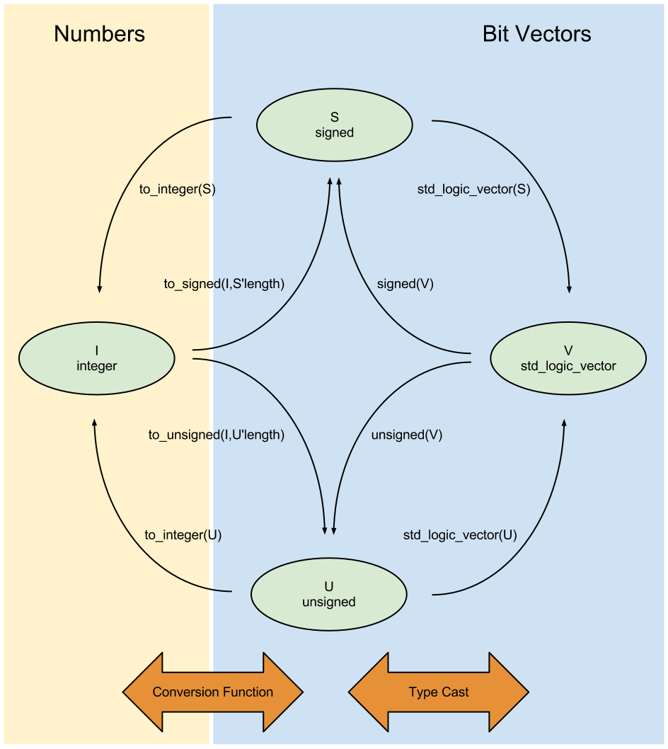
Conversion
Enumeration types
The synthesizer will automatically generate a code-table for the entries in the type definition. (It will chose automatically between binary coding, one-hot coding etc..). Useful to define states of a FSM
TYPE type_name IS (name_1,...,name_n);
Blank
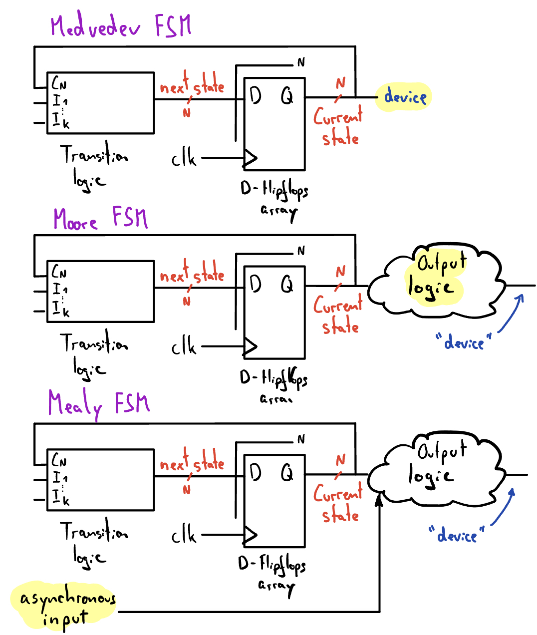
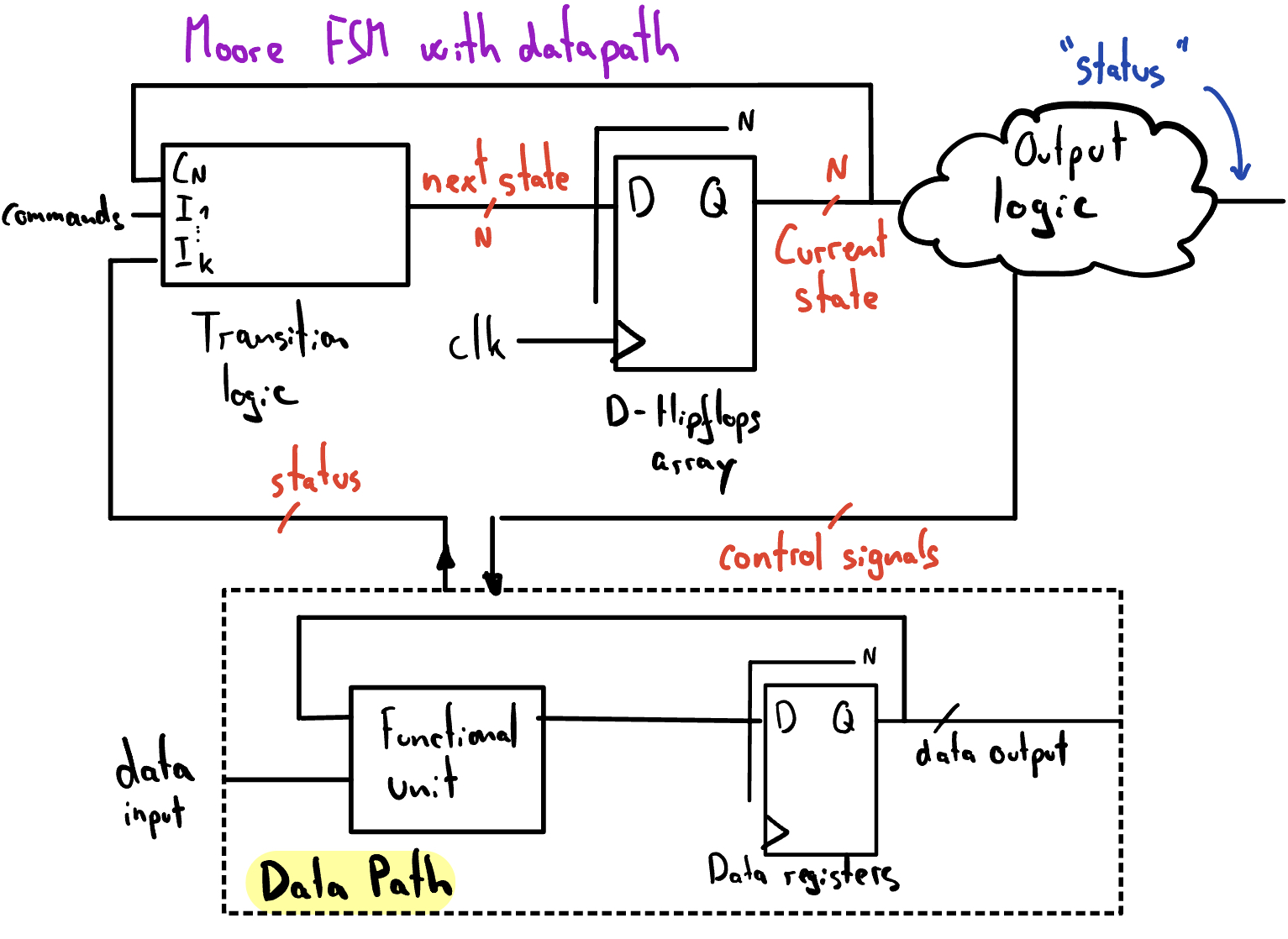
State machines : FSM
Taillights of a 1965 Ford Thunderbird
entity my_fsm is port (TOG, EN, CIK, CIR: in std_logic; Z1: out std_logic_vector(1 downto 0));end my_fsm;architecture fsm of my_fsm is type state_type is (ST0, ST1); signal s_current, s_next: state_type;begin -- Synchronous process sync_proc: process (CLK, s_next, CIR) is begin -- Take care of the asynchronous input if CLR = '1' then s_current <= ST0; elsif rising_edge(CLK) then s_current <= s_next; end if; end process sync_proc; -- Combinational process comb_proc: process (s_current, TOG, EN) is begin case s_current is when ST0 => -- Transitions regarding state ST0 if TOG = '1' then s_next <= ST1; else s_next <= ST0; end if; when ST1 => -- Transitions regarding state ST1 if TOG = '1' then s_next <= ST0; else s_next <= ST1; end if; when others => s_next <= ST0; end case; end process comb_proc; -- Output logic Z1 <= "01" when s_current = ST0 else "10";end fsm;